A well-specified Problem Statement
Many fishbone diagrams have failed because of an overly condensed, imprecisely defined problem statement. It should be replete with correlative data and information to the best of the investigating team's knowledge at the start of the project. So instead of:
Leak identified on bioreactor
Prefer something like this:
… at 12:18 on 15Oct18 a leak was identified by [name] on the nth supplement port of manifold 3B during the inoculation procedure (BR-0038).
This makes it clear:
-
how far into the inoculation it occurred
(e.g., 12 minutes into the process, which may point in a different causal direction than if it happened immediately upon opening an additive valve) -
which personnel and shift were involved
(to be able to gather immediate real-time information relevant to the activities of the process) - how often there have been issues with this process step in this particular batch record
- whether this particular piece of equipment (supplement port) has been implicated in other similar issues in the past
The investigators should be brainstorming with experts in a co-located space. Presumably everyone is looking at the board/flipchart together. The focus should be on evidence-based knowledge (EBM) techniques.
The Fishbone Diagram
There isn't one flavour of a fishbone diagram that suits all organizations.
6M Categories

Fishbone By Process Step
What happens during step 2 of the process that could have allowed this effect to occur?

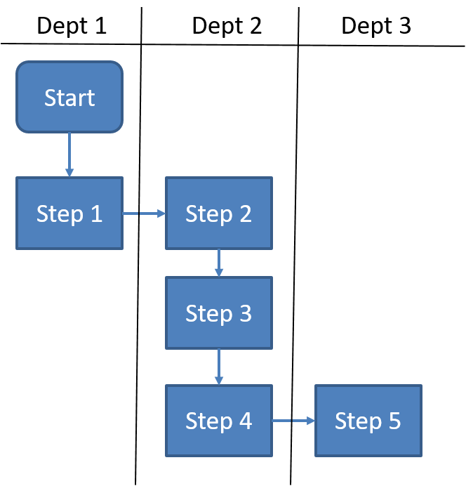
swim lanes

In Conclusion
Used consistenly and frequently, the fishbone didagram can help you identify root causes of issues (not just causal factors) and develop CAPAS to eliminate those problems.
References
- Locwin B. When to use a fishbone diagram — and why you should do it more often than you think www.pharmaceuticalonline.com/doc/…
-
Card AJ.
The problem with
5 whys
BMJ Qual Saf 2017;26:671-677. - Anderson S. Discovering Four Types of Fishbone Diagrams blog.minitab.com 06 April, 2020
- The Ultimate Guide to Fishbone Diagrams (Ishikawa / Cause and Effect) creately.com 3 February, 2021.
- The Ultimate Guide to the Fishbone Diagram leanopedia.com 11 March, 2020.